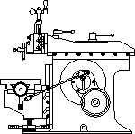

This month’s acquisition and rebuild story is from Ron Shimon in Iowa.

Lewis 10” Shaper
Photo by Ron Shimon
“In a July, 1974 issue of the Davenport, Iowa newspaper there appeared a classified ad for a “partially completed metal shaper”. I had always thought it would be nice to have a metal shaper, so I had to check this out. Also, I recalled that, many years ago, there was a company that advertised in Popular Mechanics magazine “build your own machine tools”. I wondered if this could be one of those machines. It turned out that this “partially completed metal shaper” was one of those machines, a Lewis; and it was being sold out of Harold's estate.

Shaper with Milling
Vise
Photo by Ron Shimon
Harold was a machinist by vocation and avocation. He was a machinist for one of the local farm equipment manufacturers; and he had three lathes in his basement, plus other machine tools. In one corner were patterns that he had made for castings for an engine. Harold was a bachelor, which explains how he could be so involved with his hobby.
Harold's brother was handling the estate; and had collected all of the cast iron parts for the shaper that he could find. I examined the parts and the work that had been done on them; and decided that I could finish the shaper with the equipment that I had available. So, for $65, I became the owner of the cast iron parts, drawings, bills of material, and even the packing slips. Little did I realize that I was starting a project that would take me nearly half a lifetime to finish.

Shaper Left Side
Photo by Ron Shimon
The packing list showed that Harold had ordered the No. 106 10” Metal Shaper, the No. 112 Swivel Base Vise, and the “Nuts & Screws” and “Steel and Bronze, Etc” packages for both. Harold's brother was able to find all of the castings listed on the packing list for the shaper except for the ratchet gear blank; but could only find the movable jaw for the vise. None of the “Nuts & Screws” and “Steel and Bronze, Etc” were with the shaper parts. I suspect these got mixed in with other similar materials in Harold's shop.

Shaper Right Side
Photo by Ron Shimon
In addition to the prints (actual blue prints) for the shaper and vise, there were prints for the No. 109 Mill, the No. 114 Drill Vise, and the No. 107 6” Jointer. Unfortunately, no date was shown on the packing slip, and I can't read the post mark on the envelope in which all the paperwork was sent; but it was mailed for a cent and a half. The Lewis Machine Tool Company's address on the envelope and packing list was 3217 Union Pacific Ave., Los Angeles 23, California. In other literature, I have seen the company address as 3017 North Main Street, Los Angeles 31.

Shaper Cabinet
Photo by Ron Shimon
The Lewis drawings left a lot of details up to the builder; and I didn't care for some of the details they did provide (like using set-screw collars), so I did a lot of re-design and drawing. Also I had to come up with a drive system
Harold had rough machined the 3/4 in. dovetails on the column, ram, cross rail, and cross rail slide. He had completed the base, column, sweep, and bull gear; and had slabbed off the knee and cross rail slide. He had also completed the spindle housings; however, I redid these with bronze bushings. He machined the face of the movable vise jaw; but, since I didn't have the rest of the vise, I used this piece for a lap. Not having a large mill with which to finish machine the large dovetails, I filed, lapped, and scraped these surfaces to fit.
At the time I bought the shaper, I supervised an engineering lab and model shop. I took advantage of this to do the milling work on the head, clapper box slide, clapper box, and clapper; and the sheet metal work on the belt guards. The pinion gear was obtained from Boston Gear. The remainder of the work was done with my 10 inch Atlas lathe, a home-made drill press, and a lot of tools, jigs and fixtures made especially for the project.
Early in the project, I made a set of 1/2” and 5/8”, 10 pitch left-hand ACME taps; and had a local shop heat treat them. This shop was also running a cyanide bath for some other parts that they were producing. The clapper was done at this time, so I had them case harden it in the cyanide bath. This shop was no longer in business when I made the feed ratchet gear from cold-rolled steel, so I pack case hardened it with charred leather using a charcoal fire in the Weber kettle.
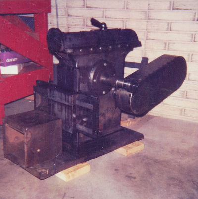
Early days
Photo by Ron Shimon
The above photo was taken in 1984. At this point, the shafts were done, gears mounted, ball-crank handles done, clapper and clapper box done, tool slide and head partially done, the bench done, and the ram would go back and forth when the input shaft was turned. In 1985 I changed jobs and worked away from home, so the shaper stayed in this condition until 2002 after I retired.
In retirement, I got back to making parts and more redesigning. This time, however, my redesign was done on a simple little CAD program on my computer. This was a big help. I also acquired an acetylene torch. Having some welding capability gave me a few more options.
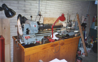
Dividing Ram Scale
Photo by Ron Shimon
Photo above shows my method for indexing to put the degree scale on the business end of the ram. That is a CAD drawn protractor taped to the sheet metal backing.
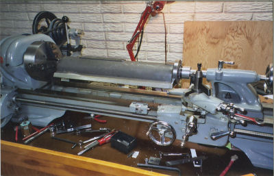
Machining Ram
Photo by Ron Shimon
The face of the ram had a hole and a recess in it. Before putting the ram in the lathe for final machining, the face was drilled and tapped so that the flanged extension could be attached. This extension sat out of the way on the lathe tailstock while the shaper ram was being machined on the lathe center. Then the extension was attached, a truing cut made on the extension, and the shaper ram supported in the steady rest. for boring the hole and recess.
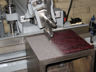
First Chips
Photo by Ron Shimon
September 2006, 32 years after I had bought the parts, the first chips were produced.

Lathe Carriage Hand
Shaper
Photo by Ron Shimon
In machining the knee, I discovered that there was a twist in the cross rail ways. When I lapped and scraped these ways, I had assumed they were cut in the same set up; so I didn't check for a twist. The error was such that the right front corner of the top of the knee was 0.005” above the plane containing the left and rear top edges. It was too much of an error to ignore. I wanted to produce flatter surfaces than that. After a lot of head scratching and procrastination, I came up with the way to fix it as shown above. Hand cranking the carriage to make it work like a shaper ram was slow; but it got the job done. What is shown is the last surface to be done. The other surfaces had already been cut and fitted to the cross rail slide by scraping.
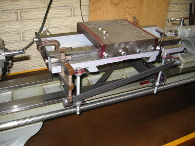
Boring Lead Screw
Hole
Photo by Ron Shimon
Correcting the ways moved them relative to the holes for the cross feed lead screw and cross feed nut. I enlarged and relocated the left-hand lead screw hole on the set-up shown in photo above. This is just an adjustable height frame that slides along the lathe ways to hold longer parts for drilling. I used this for putting in the original lead screw holes and also for center drilling the ram face. The plate on the left end contains a small hole (behind the C clamp) in the proper location for the new lead screw hole. I indicated on this hole to center the whole thing, then bored and reamed the new hole for a bushing. While in the same set-up, I drilled the lead screw hole in the new cross feed nut.
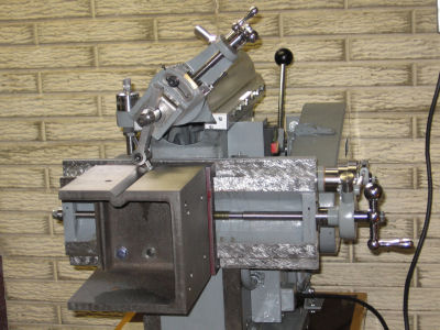
Cutting V groove
Photo by Ron Shimon
With the cross rail ways corrected, it was back to machining the knee. The knee casting had a boss for a V groove on the side.
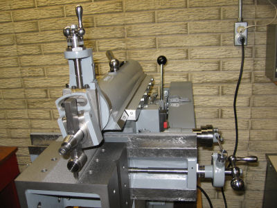
Final Cut of Knee
Photo by Ron Shimon
April 2008, (34 years after I bought the parts) the final cut on the knee takes place. Now all that remained was to install the rest of the wipers which had already been made.
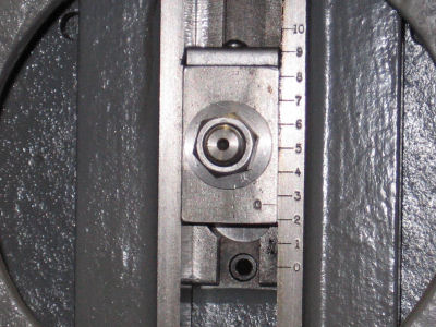
Length Adjustment
Photo by Ron Shimon
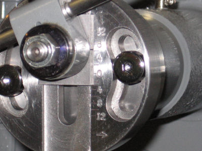
Pawl Adjustment
Photo by Ron Shimon
I don't know how many hours I put on this project; but they were all fun hours. The biggest challenge was to figure out a way to make stuff using the tools available. I'm pleased with the way the shaper turned out. And I think Harold would be too.”
Thanks Ron for that great acquisition and rebuild story.
Keep sending me email with questions and interesting shaper stories.
My email address is KayPatFisher@gmail.com.