Since the highest setting with approx.120 cuts/min is quite a load for the old machine and also since I was able to lay my hands on an old VFD, the machine was converted for lower speed settings.
The 380 Volt VFD is a vintage part with at least 20 years on it. I’m happy about everything concerning manufacturer and type.
No computer is part of this electronics. Just discrete logic!
Caused by the age of the VFD, a few electrolytic capacitors blew up during the first hours of the VFD’s new life. However, after removal of the faulty parts, the machine is willing to cooperate again.
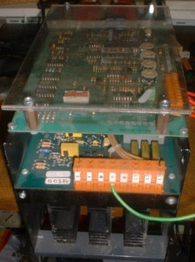
Discrete VFD
Photo by Siegfried Schmidt
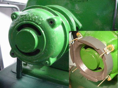
The VFD is a tight fit in the cabinet. The heat sink is cooled by an oversized fan, which is even louder than the motor.
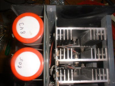
VFD Electrolytics
Photo by Siegfried Schmidt
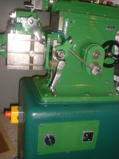
Below is the old front plate with new interior. The over current protection was removed. Just the mains switch and crank speed control remain. Start/Stop of the VFD is set via a rheostat, like in a good old radio. The knob on the outside comes from the good old times and also looks like it!
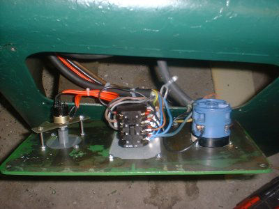
VFD Controls
Photo by Siegfried Schmidt
The decision for the VFD was good. The motor can be driven with 0-100 Hz; the motor itself is set to the lower revolution range. By this setting, all former drive speeds can be achieved.
VFD on Front Plate
Photo by Siegfried Schmidt
Not every speed setting is necessary, but with the VFD, very slow revolutions of the crank are possible to test the machine’s setting. Another advantage is the possibility to stop quickly. Without the VFD, the machine would travel another half revolution after power was removed.
Before conversion, lots of cranking was necessary for setup. After conversion, the hand crank is no longer necessary.
During operation, I found out that the fan in the motor was not sufficient at low driving speeds. Maybe the small venting slots are the problem. Anyhow, serious work with low operation speeds sent the motor temperature to unhealthy regions quickly.
Motor Cooling Bracket
Photo by Siegfried Schmidt
Since motor and side cover is a unit, I didn’t want to risk the premature death of the motor. There’s no easy way to improve the built in forced-air cooling, so I added an external 120mm fan.
The plastic flange shown below between the fan and the motor looks rather bad. Also, the small slots slow the moving air, but enough air comes through to keep the motor cool.
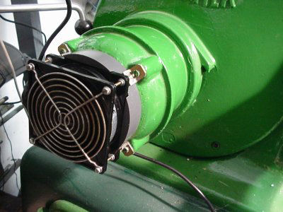
Motor with Fan
Photo by Siegfried Schmidt
The most surprising fact is a mill and a shaper go hand-in-hand quite well. Every time setting up or machining imposes problems on one kind of machine, the other jumps in and helps out. The classic impossibilities of a mill (internal keyways, internal gears) are not the real problems; it’s rather the small things that help a lot.
Cut-outs with sloped sides are an example. Where setting up and cutting with a mill is problematic or at least time consuming, cuts are easily achieved with the shaper.
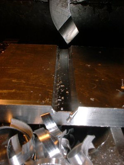
Slots with slope
Photo by Siegfried Schmidt
Also, a simple lathe tool leaves surface finishes impossible to achieve with a mill, at least for me.
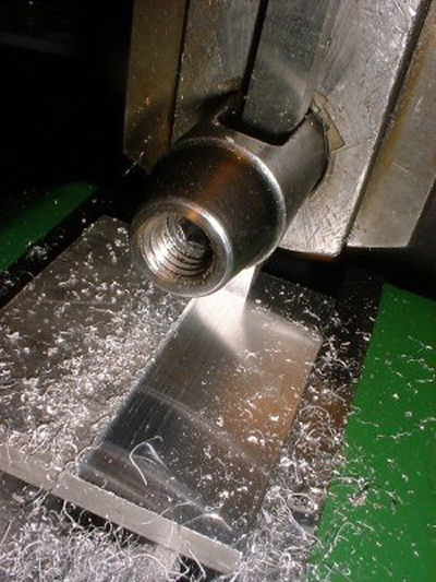
Shaper Surface Finish
Photo by Siegfried Schmidt
Cutting of gears or knurling with the shaper is much easier than with a mill. The shaper needs less headroom.
In the same setup, milling with a disc cutter or a gear cutter would be critical, because there’s not as much room.
Shaping a Gear
Photo by Siegfried Schmidt
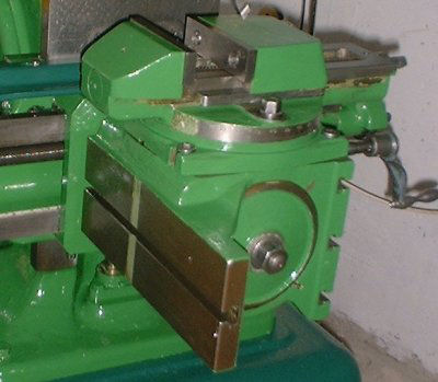
I was able to hunt down some documentation to clear up the details. The right side of the table with its three slots is for direct work mounting. A v-groove for round parts is included. There is also a bigger auxiliary table that can be attached here. Until now, I found no picture for this delicate part of special tooling.
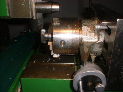
The long, single slide to the left is dedicated to mount a dividing fixture, like in the next picture.
For precision work, the setup of the machine can be altered for a draw cut. Draw cutting preserves layout lines. Also, when draw cutting, chips fly away from the operator.”
Left Side of Table
Photo by Siegfried Schmidt
Next month we will examine grinding with Siegfried Schmidt’s Ludwig Gack Shaper.
Keep sending me email with questions and interesting shaper stories.
My email address is KayPatFisher@gmail.com.