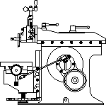
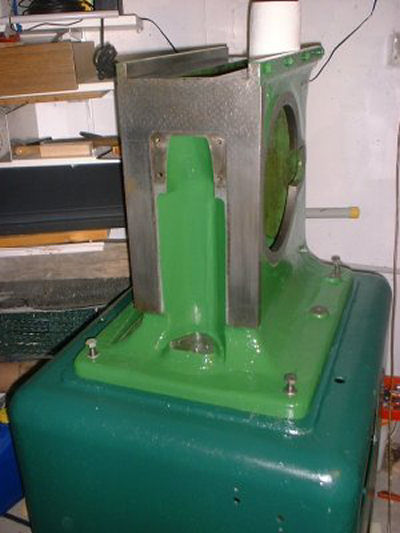
Base and Column
Photo by Siegfried Schmidt
The biggest parts are reunited first. The main body is attached to the base by four screws and a cable.
The crank with the feed gear was installed next. The two shiny areas on the main body are there to attach a chip pan.
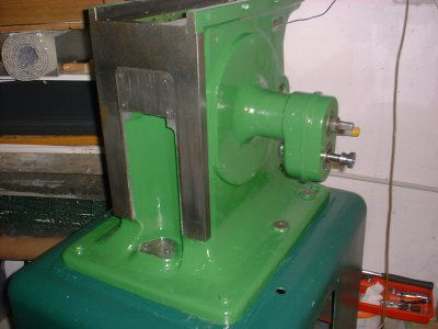
Feed Gear Installed
Photo by Siegfried Schmidt
The machine’s ram and rocker arms are back to work again. The parts for transmission of the load look rather flimsy. Despite this, no signs of wear were visible, even after 50 years. Since it stood this much time and use, I guess it will do the same again.
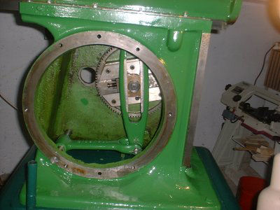
Ram & Insides
Photo by Siegfried Schmidt
The worktable is back! Vise and t-slotted table are carried by the cylinder and are then tightened down via the central nut. The table can be set in any angle; additionally there are holes on the cylinder for quick setup of special angles.
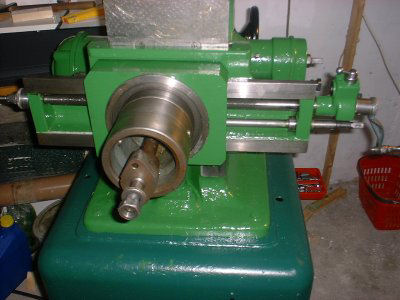
Table Installed
Photo by Siegfried Schmidt
To the left, a plunger can be seen that sets the table to given angles via the holes in the cylinder. The graduation is only needed for special angles. The vertical spindle is mounted rigidly to the machine housing. The worm drive moves the slide up and down by screwing the worm gear up and down on the fixed screw. This is quite a cool idea!
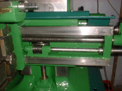
Table Close-up
Photo by Siegfried Schmidt
The ratchet for auto feed can be taken off the horizontal feed and attached to the vertical feed. This is another super cool idea.
Movement of the screw on the feed gear sets feed. I won’t go into depth here; all shaperists are familiar with this.
On top of the feed ratchet, direction of travel can be set with the small handle. Also, it can be shut off completely here.
Feed Ratchet
Photo by Siegfried Schmidt
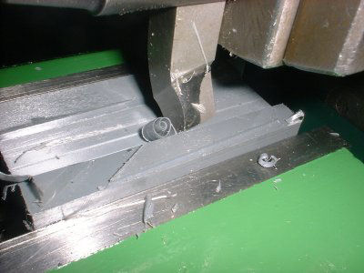
Now, the machine is ready for the first test cuts. The only things missing are the final electric setup with a VFD, fine-tuning of the ram gibs, paint touch-up, installation of a work light, and reattachment of the chip pan.
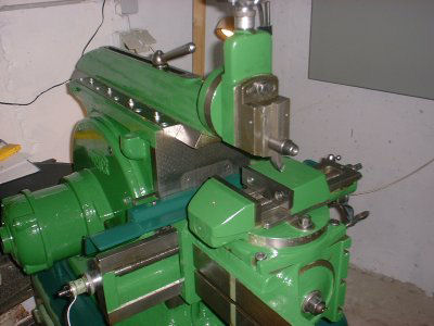
Nearly Ready
Photo by Siegfried Schmidt
Here is the first curl. For safety reasons, I tested it with plastic. A second clapper box that cuts on drag, not on the pushing motion of the ram, was also part of the machine. With it, the machine cuts on the rearward travel, which makes necessary the alternate direction of rotation. This lets the operator see scribed lines on the work piece. Also, this causes chips to fly away from the operator.
First Cut
Photo by Siegfried Schmidt
What moves can be observed. And here, in the drive-line, a lot of parts move. It’s a pity no movement is seen in the assembled state - only the rhythmic noise of the machine.
In the assembled state, the drive is no longer visible completely, so I will explain it with the two pictures that follow.
In most shapers, for height reasons, the crank is split in two links.
In this shaper, the problem is solved in a different way.
The link is connected to the housing of the machine via another crank and is able to move at a constant height.
There is a single link in position D. The crank is connected to another link arm (A-B) which can compensate the height movement.
This rare design results in rather complicated kinematics, since the length of the link changes in relation to the slide and also in relation to the slide block.
Because of the change of link ratio during one rotation, the direction of travel is locked to the direction of the tool. The head has to move slowly during cut and fast during the retract cycle. This movement is superimposed with the up and down travel of the crank.
During the retract cycle, the lowering of the crank aids in braking the slide motion. Seen over the whole cut, the ram moves with a little more even speed. Even small alterations here can have large effects, since, added to cutting forces, the masses of the slide must be accelerated and decelerated.
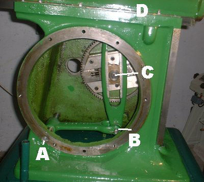
Height Corrector
Photo by Siegfried Schmidt
While looking at the links, two bumps were found in the main body of the machine. Possibly, it was planned to add an axle here that can aid as another support for the link. Another possibility is that a rigid mount of the rocker arm was planned here for another version of the machine. By looking at the picture, one can estimate that a rocker arm with a second link attached to the slide in a more classical design could be put here quite reasonable.
Axle A has no reinforcements of the castings in the place it’s mounted. It’s housed in the same place corresponding to the side cover as the two bumps. The axle is secured in its position by the cover.
The question of lubing and of the kind of lube was not answered for quite a while. The grease seen in the following pictures is not the right lube, but there were no bad effects found on the machine. Lucky me!
Since the machine’s body forms an enclosure, the bearings are only accessible indirectly.
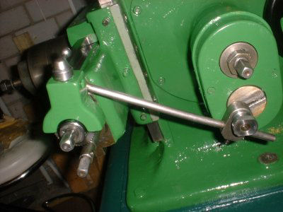
Axle (A) is lubricated via an oil port and a hollow shaft. All other bearings (B, C, & E) are oiled via the oil port visible in the ram position lock. I was astounded to see deep dents on the handle. There is no need to tighten it with a hammer!
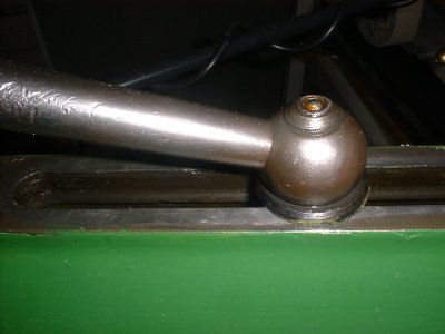
Ram Handle
Photo by Siegfried Schmidt
Below is a photo of the rocker arm in its raw state. On top is the (hollow) connection to the ram. To the left, the link shaft is seen.
The bearing is drilled through on top, so the oil can move through to the rocker arm, into the bearing and downwards from there. There’s a small oil guide cut on the rocker arm. After lubing of the link shaft, the oil travels on via the small gunmetal pipe.
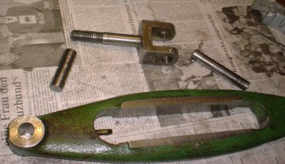
Rocker Arm
Photo by Siegfried Schmidt
Directly under the pipe is the crank block. Here, oil drips into the cylindrical indent and is distributed towards the outer sliding surfaces and the crank block’s central bearing. At least that’s how it’s planned if there’s no grease in the way.
Crank Block
Photo by Siegfried Schmidt
But the oil is not done yet. Oil from the slide way sags down and gets caught in v-shaped cut outs on both sides of the lower link shaft, which is lubed in this way.”
Drive Link
Photo by Siegfried Schmidt
Next month we will continue with the electronics of Siegfried Schmidt’s Ludwig Gack Shaper.
Keep sending me email with questions and interesting shaper stories.
My email address is KayPatFisher@gmail.com.