This month we will continue our story of Ludwig Siegfried Schmidt’s Gack Shaper.
Since it’s not only a very big paperweight, the machine was intended to do some work from time to time; so I had to restore the electrical installation also.
In these pictures, the painted surfaces look flat and shining, the old scratches and dings in the paint are not hidden under body putty. This can be fixed some time later. I think it will not bother me later since it does not bother me now.
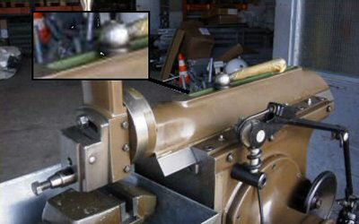
Military Gack
Photo source unknown
Quite early, the question of the original color arose. The faded green is, as far as I can see, not the original color. Further, it’s worn away, and not a good base for a new paint job.
The luscious green on the inside seems to be original; there are no signs of touch up work there. Inside the worktable, I found grey colors, which are mentioned as the original outside color by some online sources.
Pictured above is a military machine, the inside of which is also shiny green.
This gave rise to a green paint job. If the machine was grey before, then shame on me but I like the green much more.
The tool head and the rotating worktable gave the fewest problems at all. Everything was shiny, the table’s surface was straight and the rest only needed a few drops of fresh paint.
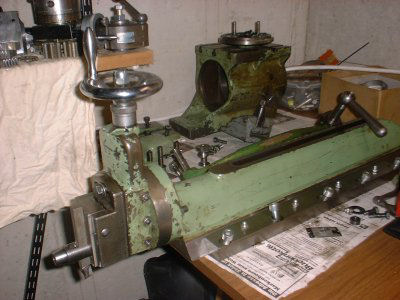
Ram
Photo by Siegfried Schmidt
The machine’s main body bore the year of manufacture. Some of the machine’s parts were stamped “6” with a punch. Below the grime, good surfaces showed up. On some parts, the scraping marks were still present.
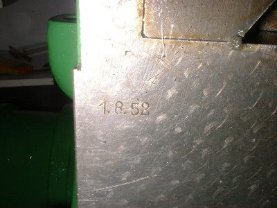
Serial Number
Photo by Siegfried Schmidt
The heart of the machine, the die block of the rocker arm, was preserved in remarkably good condition, without signs of wear. Beyond cleaning, nothing was left to do here. The setting of the machine’s stroke is done through the hollow shaft of the crank drive via a joint to the spindle in the picture below.
Crank Pin Assembly
Photo by Siegfried Schmidt
The crank gear is made of fabric-reinforced phenolic resin and will perform its duty.
In the photo below, the shaft is going out of the machine on the left hand side onto a hand crank where there is no rest or bearing. The black ring to the left is next to the housing, but not touching it. To the right of the gear is a shiny nut for setting bearing clearance. It is attached to the gear with two pins that fit between two voids in the gear. In the housing to the right sits another reduction gear.
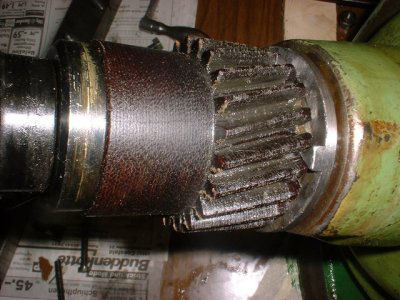
Drive Shaft
Photo by Siegfried Schmidt
The first reduction gear housing is attached to the inside of the big side cover. The cover is screwed and pinned to the machines body.
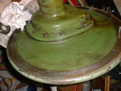
Side Cover
Photo by Siegfried Schmidt
The drive is attached to the cover. The inner bearing of the motor is cast in place. The motor is screwed to the cover. The air from forced motor cooling escapes through the side vents.
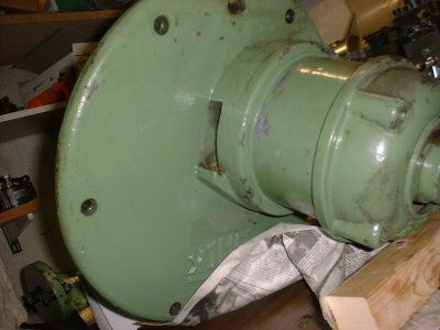
Motor on Cover
Photo by Siegfried Schmidt
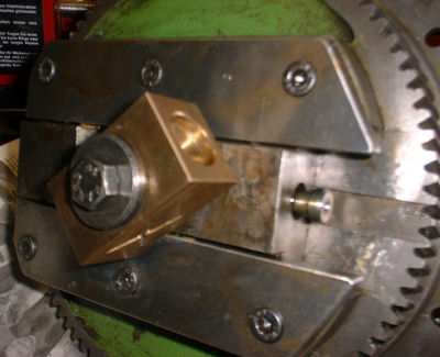
Because of the hollow drive shaft for the crank, a separate gear is necessary for the table feed. In the photo below, the square to the right is for setting of the machine’s stroke. The moveable screw sets the table feed. Here, the pushed on gears again act as a counterpart for the setting of the bearing clearance. The rings have corresponding noses that fit in the voids of the gears.
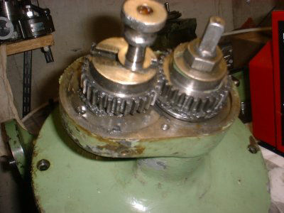
Table Feed Gears
Photo by Siegfried Schmidt
The old hole is bored to the size of the new mains switch.
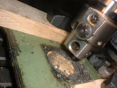
Hole for Switch
Photo by Siegfried Schmidt
The mounting of the lower rocker arm is a pressed in pin that I didn’t take out. Some paint was enough to install the full glory of this part. The writing on the part is not really known (my guess: H185 is the machine type).”
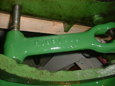
Rocker Arm
Photo by Siegfried Schmidt
Next month we will continue with the assembly of Siegfried Schmidt’s Ludwig Gack Shaper.
Keep sending me email with questions and interesting shaper stories.
My email address is KayPatFisher@gmail.com.