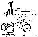

This month’s shaper story is from Geoff Kingma in Ontario Canada.

6" AMMCO Shaper
Photo by Geoff Kingma
“In June, 2003, I purchased a 6” AMMCO Shaper. It was complete except for the belt guards. This shaper was designated as a 6” unit but it actually has a 7” maximum stroke.
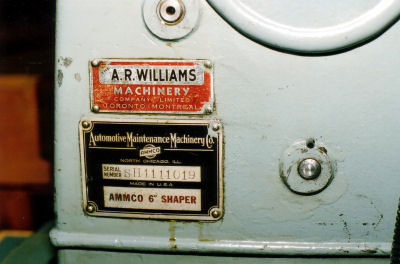
Shaper Label
Photo by Geoff Kingma
The 6” model manufactured until 1941 has the drive unit mounted behind the machine but mounting it below, as the previous owner had done, was an excellent idea since the depth of the stand could be reduced. The table elevating screw is underneath the base. Sometime in late 1941 or early 1942, the 7” model was introduced, with the elevating crank coming out on the right side of the base casting. Other changes included 3 oilers on each side of the ram ways (vs. 1) and the motor/countershaft unit nestled up vertically behind the main body.
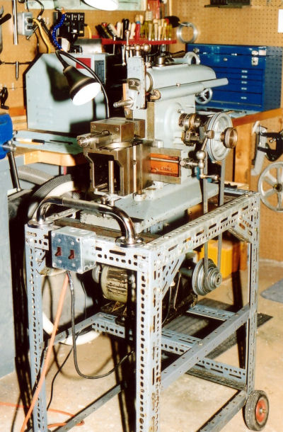
Old Shaper Stand
Photo by Geoff Kingma
I found a number stamped on the underside of the ram protector casting that reads “01 : 40”. I am not sure about the “1” as it is indistinct and could be a “2”. So perhaps it was cast in 1940.
This machine originally came with a flat belt and pulleys (counter shaft to pinion shaft). I guess that it was changed to v-belts sometime in the early 1950s when Ontario’s electrical systems changed from 25 cycles to 60 cycles AC. A new motor would have to have been installed. This motor is a Tamper Electric 1/3-HP unit which appears to be the correct vintage.
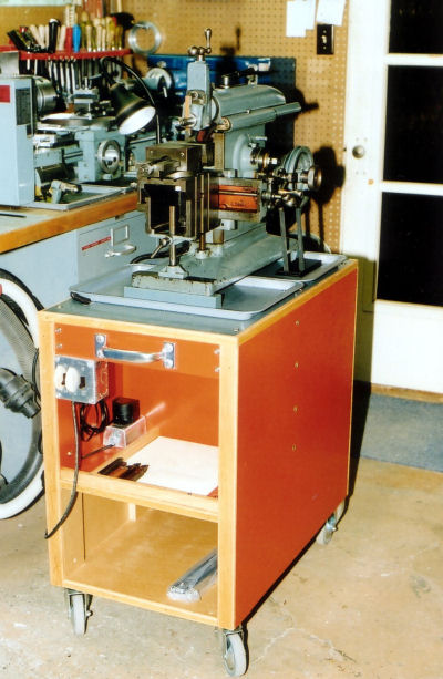
New Shaper Stand
Photo by Geoff Kingma
It had been mounted on a Dexion frame but wasn’t very stable due to a lack of mass and no locking castors.
My first task was to make a plywood stand. This has double side panels (1.5” thick) and angle iron cross members under the mounting holes to strengthen the top. The drawer had not yet been finished when I took the photo. I used an entire 4 x 8 sheet of ¾” plywood for the stand and mounted it on 4” castors with brakes on the front swiveling units. The edging is recycled oak flooring strips. Now it is stable and can be moved easily.
I used it until late 2004, getting to know its capabilities and being fascinated and hypnotized by the rhythmic motion as it cut metal. The finish was quite good but it wasn’t very accurate when blocks machined on it were measured front to back and side to side. I also found that I could not ever get the ram gibs adjusted correctly – if I adjusted it correctly for a short stroke operation, it would be too tight when a long stroke job was required. Also, the cross feed table gibs couldn’t be adjusted correctly – good on one side was too tight on the other. In addition all the bearings were sloppy so there was a good deal of “clanking” when it operated.
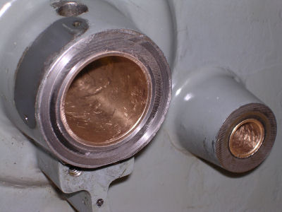
New Bushings
Photo by Geoff Kingma
In December of 2004 I decided it was time for a rebuild. All the bushings (available from Boston Gear) and most of the shafts were replaced and the cross feed eccentric was rebored and sleeved. A new rocker arm shoe was made from 660 bronze as the previous one had been attacked by a hammer. After replacing the two bushes for the pinion shaft, I found that the one opposite the drive side was located 0.017” lower.
Putting the main frame on my Taig Mill to rebore the hole was a trifle tricky but worked out well. The new shaft I had made slid in freely but with no discernible play.
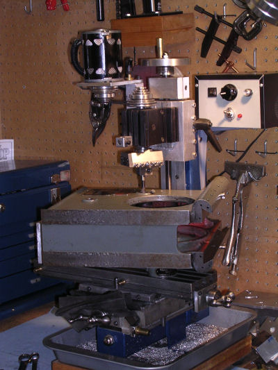
Boring Bushing on Taig
Photo by Geoff Kingma
I can only figure that the original pinion bushings had been line bored/reamed on an angle. Was this machine assembled on a Monday?
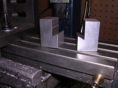
V Blocks
Photo by Geoff Kingma
After I pressed in the new bull gear bushing, it was slightly too tight a fit. This is where scraping was in order as I don’t have a 1 3/8” diameter reamer. To my surprise it worked and I was able to get the 0.0015” clearance required.
I then made a matched pair of V-way blocks to support the cross rail. When I measured the width of the cross rail (placed on these blocks on a surface plate) it was 0.006” wider on the right side than the left. No wonder gib adjustment was a problem.
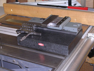
Measuring Cross Rail
Photo by Geoff Kingma
Mounting it on the Taig was a challenge. The piece of wood (1/8” plywood) between the angle plate and the casting was to give clearance for the cutter as both parts happened to be the same height.
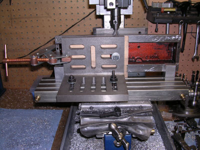
Cross Rail on Taig
Photo by Geoff Kingma

Cross Rail on Taig Side
Photo by Geoff Kingma
Since the X-travel on the Taig is less than the part length, some creative sliding was required. When I remounted the table to the cross rail to check for fit, it was amazing how smooth it was with the gib snugged up.
I had scraped out some minor errors on the ways. It was probably not needed but was satisfying to see the improvement in “spots per inch”. However, I have a long way to go as far as neat scrape marks are concerned!
Next came the vertical ways on the main frame.

Measuring Vertical Wear
Photo by Geoff Kingma
The results from measuring was a lean to the right of 0.007’ over 4½” of vertical travel. The top of the cross rail had been machined parallel to the shoe support on the base casting. I am beginning to think that this shaper had been made on the day after a long weekend!
So, after a quick calculation, I figured that a 0.002” shim placed under the right side between the main frame and base was a good starting point. Separating the base from the frame was easy (6 bolts under original red paint). I cleaned up some crud on the mounting surfaces and re-assembled ot after inserting the shim strip. Measuring again reveals a lean to the left!
Out with the shim and voila – perfect.
To verify that all was ok, I put a 0.001” feeler under the shoe when the table was at the left and then checked at the opposite end. Result: no difference. Was this machine actually assembled the day after an annual shutdown?
The vice was next. The round base was checked for height on the surface place and there was a 0.0015” difference from low to high point. Cleaning up both surfaces, re-countersinking one mounting screw hole and a skim in the lathe brought it back to no movement on the indicator. Next the assembled vice was placed on 1-2-3 blocks and the bed was checked. Now there was less than 0.0005” variation. I figure I’ll leave it for now.
Stripping was next. I used “Citrus Strip” and was pleased with the results. As long as the stripper was not left on too long, I found that it did not affect the filler material used on the casting. However, many spots had to be refilled due to dings and bangs over the years. I used a two-part auto body filler to patch those spots and the ones where the stripper was left in place too long (I learned quickly).
All the flat metal surfaces were cleaned using a sheet of 400 (wet-or-dry) on a glass plate with oil as the lubricant. Round parts were buffed clean. After masking off the exposed metal areas I sprayed the castings with grey auto primer from an aerosol can.

Gray Auto Primer
Photo by Geoff Kingma
The final but most complicated item was the V-ways on the ram and main frame. Measuring the height of the way on the frame showed a drop of 0.005” from back to front. More problematic was that the sloping part of the way was 0.012” wider at the front compared to the rear. No wonder I couldn’t adjust the gib. The gib itself was 0.005” narrower in the middle compared to the ends. To help minimize future wear, I drilled 4 extra holes for oilers in the frame per the 7” model.

Milling Ram V-Way
Photo by Geoff Kingma
The frame was clearly too big to fit vertically in my Taig Mill so I called a fellow model club member. Before I went to his shop I had to get a 60 degree dovetail cutter of a size to do the ram and frame. This cutter was huge for my small mill but his mill was up to the task. The ram was bolted to the mill bed with a bar machined to fit the shaper vertical slide hole and also through the ram adjuster locking slot. Only a few thou had to be taken off the top (bottom) surface and v-way to true it.

Clapper After
Photo by Geoff Kingma
The main frame was next and I located it using the gib side as a reference. This took over an hour. First the horizontal part of the ways were machined. Then I raised the quill by 0.003” and proceeded to machine the sloping part of the way opposite the gib side. This took a while as I only cut 0.002” per pass. Cutters this big make lots of noise in a hollow casting! It was amazing to see how the part had worn in an undulating pattern. As each pass was completed, some high spots disappear. Someone suggested that I use power feed to get a smooth surface. I did one pass manually feeding the table and was amazed how different the surface was, even though the mill’s table appeared to have no play. This operation took the better part of a day to complete.

Old AMMCO Decal
Photo by Cecil Walker
Once I got back to my place I realized that the new gib strip had to be wider than the original. I picked up a piece of 3/16” ground stock and cut the required angles on the Taig using the “sliding” method once again. After a quick clean up of machined surfaces, a check was done on the ram assembled in the frame with the new gib snugged up. It was smooth and consistent over the full length.

New AMMCO Decal
Photo by Geoff Kingma
After repainting using Varathane Liquid Plastic grey with a touch of blue added (a fairly large touch) and automotive engine enamel red, assembly could finally begin. New oilers from MSC were installed and the felts on the rocker arm shoe and ram ways was replaced. Even though the cross feed nut is worn, I left it as is since a bit of backlash isn’t an issue.
The logo for the door was recreated by my son from a photo kindly sent to me by Cecil Walker, who has an original unrestored machine. My son used some high powered software to recreate the logo. To get it to print properly (at the correct size), he put 8 images on a page which took up 10Mb of memory. This "fixed" them to the correct width and height. About 8 members of the Yahoo chat group requested copies so I printed the images onto a transparency (for overhead projectors - becoming extinct!) with a reversed image so that the ink side would be protected. I stuck it onto the door with 3M #77 spray adhesive. I think it will last longer than the original which appears to be very thin and brittle. I don't think Mylar based plastic had been invented in those days. The only problem is that I probably won't be around long enough to verify this.
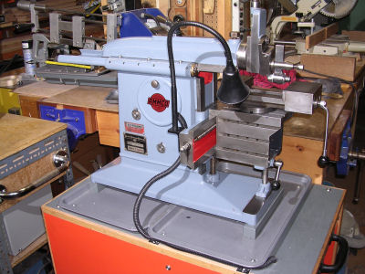
AMMCO Shaper After
Photo by Geoff Kingma
On my first test run, I was amazed how quietly it ran. The only sounds were hum from the motor along with the click/hiss as it peeled metal. I used the machine to skim the table as it was about 0.005” higher at the front than the back. It is able to cut front to back within 0.002” over 6” and is less than 0.001” side to side. After running it in for a while, I’ll do another check and maybe true up the vice to get this down to less than 0.001”.
It was a fun project and I am now a very happy camper. I figure that with proper lubrication which it lacked in the past, this baby is good for another 50 years. I am using SAE 20 way oil which doesn’t seem to evaporate as does straight non-detergent oil and it sticks on surfaces - highly recommended.”
Thanks Geoff for that great story and pictures.
Keep sending me email with questions and interesting shaper stories.
My email address is KayPatFisher@gmail.com.