Clock ahead to spring 2002:
In the months following my initial introduction to Alba, much has transpired.
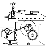
In the time that Alba and I have been getting acquainted, I have been plagued with a clunking noise from the drive mechanism, as I described in my last installment.
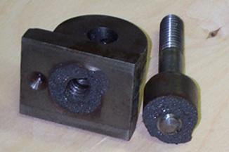
One of the first jobs I set Alba to work on was a replacement slide block for the link arm. I took much care and measured twice and ended up with a block that was right on the money this time (.002" clearance).
When I installed this new block and tried again, I was still getting strange noises, particularly under load. I found this very vexing and one evening, in a fit of frustration, (well not quite) I took the link arm out. I measured things to see what was wrong. The slide block was OK, but the fixed end was loose on the pivot pin.
I measured again! Sure enough, the slots in the link arm measured 1.260" instead of the 1.250" that they should be.
I thought that I had been pretty careful about measuring this before, so I was having a hard time understanding what had happened here. I puzzled over this and made more measurements. Then I got the right piece in my hand! The culprit was the insert tooth end mill I had bought to machine the slots.
This particular tool had been made in Europe. When I measured across the edges with my vernier, I discovered that it was .010" over. This explained a lot about the loose slide block, and now the fixed end slot.
The new problem with the fixed end caused me several evenings of thought on how to fix it. Readers may remember that the link arm was made from a machined weldment, and a lump of 1 ¼" thick steel doesn't grow too easily.
I finally came up with a solution, which I thought was actually quite elegant. I machined the thicker of the two sides back .115" and added a .125" CRS plate, attached with 4 each 6/32 counter sunk cap screws. This made up the excess clearance and also provided for adjustment of any future wear by adding a small shim.
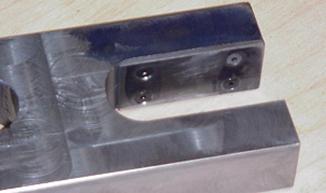
Fixed End Repair Photo by Pete Verbree
I reinstalled the link arm and set Alba to work again. A large improvement was realized, but that pesky clunk was still there!
Now What? I watched, I measured, I fiddled, I adjusted! No use, it was still there!
I put a large block of steel on the table and started the machine on slow auto-feed. I went around to the side, opened the cover, and with a mirror and flashlight watched again. The bull gear appeared to move back and forth in a side-to-side motion. HUH? That's odd; I put new bushings on that shaft when I first repaired this.
Further disassembly and careful measurement provided the answer. The shaft had been worn slightly oval. Not much, only .005-.006". However, on the inboard end it was on the back, and on the outboard end it was on the front, effectively doubling the bull gear movement.
I sat and pondered this some, and came to the realization that the thrust of the cut put more load on the back of the shaft than on the front.
The reason that this wasn't obvious in the beginning was the new bushings I had installed didn't ride on the shaft in exactly the same spot as the old. This allowed the shaft to run normally until the small shoulder wore away the bushing and the clearance showed up again.
To repair this I placed the shaft between centers in my lathe, and turned it until it was round again, about .015" undersize. The reduction in size of the shaft now demanded custom bushings. I turned them from a piece of bronze and pressed them into place.
Simple enough! Yeah, Right!
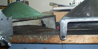
We all know that bushings will collapse a little when pressed into place; the trouble with this job was I tried to get them too close, and when I pressed them in they were too tight!
I didn't have a reamer that big, and it was an odd size so I elected to set them up in the lathe and bore them to size (very carefully).
When I finally was able to reassemble the machine and test run it again, the difference was remarkable. The only noise was the gears loading and unloading; the clunk was almost completely gone.
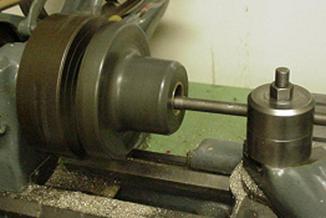
Boring the New Bushings Photo by Pete Verbree
By chance, I found another Alba 1a in the good care of an acquaintance in Sault Ste Marie (about 4 hrs drive away). Merv Punkari runs a small, but busy, aircraft repair shop. I knew that he had several pieces of metalworking machinery to support his business. I visited Merv's facility in April, during the course of my job as a safety inspector. I was looking around in a workshop and low and behold I spied what looked to be a small shaper! With much apprehension, I crept closer. Sure enough a "cherry" Alba 1a complete right down to the tool holder.
Well as you can imagine this was cause for much conversation at coffee time. Merv, being the gentleman that he is, offered to lend me the large pulley cover to use as a pattern for a replacement. Yee Haw!
I brought the cover home and tried it on my machine. It was a perfect fit; I didn't even have to adjust the latch! Now the scheming and plotting started up in earnest again. Where was I going to get a casting made?
Several inquiries later lead me to Well's Foundry in London Ontario. They responded to my inquiry with a quote of $80.00, plus tax and shipping. Boy oh boy, I can't wait for my next allowance!
In due course the cover made its way to and from the foundry and I don't think I could be any happier with the result!
New Cover and Pattern Photo by Pete Verbree
During the time that the cover was at the foundry, a small disaster occurred while using the shaper to fabricate a vise. The upper hinge on the ram lever broke while I was tightening the nut. I suspect that this is a result of the abuse that was handed to this machine in the past. Temporary repairs had to be made again! Do we see a trend here?
Broken Upper Hinge Photo by Pete Verbree
I cobbled the upper hinge back together enough to run the machine, and went "on the scrounge" for a piece of cast iron to machine a replacement out of. While the shaper was out of service, I figured that I could use the time to install the new cover on the shaper (Patience turned off).
I carefully laid out the location of the hole and scratched my head as to how I would drill it. It is drilled vertically from the bottom. It was too big for the mill/drill and quite an awkward shape to hold on the drill press table.
With my chest puffed out and my ego switched onto full, I decided to set it in the bench vise and drill it by eye (patience still turned off). I lined up as best as I could and charged ahead.
"Not bad thinks I, let's try it on the machine".
Well, it fit on the hinge pin all right, but it leaned a little to the right. "What's wrong?"
I laid the piece on the bench next to the pattern and sized it up. It turned out that I had drilled the hole at a slight angle, and no amount of fiddling would make the cover close properly.
Ok, I can fix this. I made a plug of cast iron rod and plug the hole and re-drilled. No sweat!
The next attempt to drill the hole resulted in an equally bad result and I now had a big problem: Two botched, overlapping, misaligned ½" holes!
Jig and Botched Holes Photo by Pete Verbree
In the picture you can see the botched holes with the first repair plug removed.
When I finally got the patience turned on and the ego turned off, I dreamed up a jig to align the hand drill and guide the bit. I used a freshly sharpened 5/8" bit to clean up the hole and get it into alignment. I then fabricated a long bushing and Loctite-ed it into place. A little metal reinforced epoxy filled the remaining gaps and believe it or not the cover now fits reasonably well.
There is a small gap on the hinge line but the average horse will not notice as it gallops by. Boy, I wish I'd slowed down and thought up the jig in the first place!
Cover Finally Installed Photo by Pete Verbree
I made another trip to my favorite machine shop and managed to talk them out of a cutoff piece of cast iron bar, big enough to fabricate a new link arm upper hinge.
I squared up the block in the shaper and then marked it out for further work on the mill/drill.
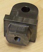
New Upper Hinge Photo by Pete Verbree
This piece was not particularly tough to make but care was taken to make the piece straight and square. I did modify the original design slightly to increase the size of the hub on the top for the lock bolt on the top. Readers will note that it is now oval as opposed to round.
The completion of the upper hinge marked a milestone in this project. I believe that I have repaired all the damage from Alba's former life. Time to make her pretty again.
When Alba arrived in my care she was wearing a coat of medium dark machine tool gray, with red trim. A little "dowdy" in my opinion.
I e-mailed Frank about his machine, and he responded that it was green, although not original in his opinion. Merv Punkari's machine is also green. Hmm!
I read the archives of several of the newsgroups I frequent on the Internet, but was not able to come up with a definitive answer as to the "proper" color for machine tools. There seems to be about 11 opinions for every 10 persons asked!
During my research, I stumbled across a picture of a lathe painted a very attractive grey/green color. I'm not real good at this color stuff, but for a "coming out party" I thought a little effort was in order. So off I trek to the local industrial supply to check out the paint chips.
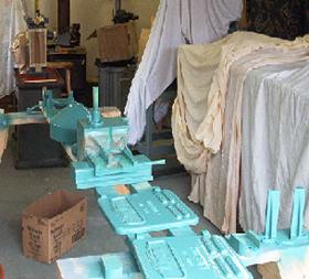
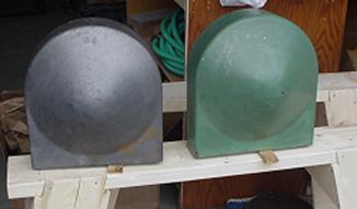
Parts Being Painted Photo by Pete Verbree
I found a color called "Detroit Diesel green" that I liked. This being a special occasion and all, I called in the "expert" (loving wife Leanne, who helps pick out my clothes and generally keeps me from clashing too often) to keep me out of trouble.
Leanne confirmed that the color was quite suitable, so a deal was struck for 1 quart of acrylic enamel and associated "stuff".
A proper paint job would require complete disassembly, strip, prime and re-paint. I had waited too long to spend that much time fussing on finish, so I elected for a partial disassembly and sand before painting.
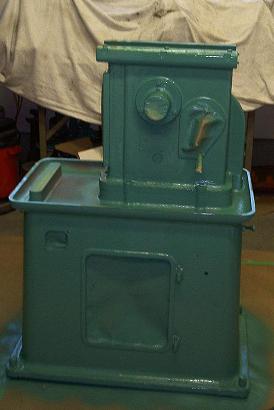
Base and Pedestal in Paint Photo by Pete Verbree
Time for a little reflection:
I expect that the reasons we play at metalworking as a hobby vary as much as the people who do it. When ever my wife asks, (usually after some big FUBAR on my account) "Why do you torture yourself like that?" My usual answer is that it teaches humility. It teaches me to slow down and smell the cutting oil, and to think about what it is I am about to do. My experience with the large pulley cover really gave me a large dose of humility!
I would like to take a couple of lines to thank those who helped me with this project. It sure wasn't a solo effort.
To My wife Leanne: Thanks for the patience. To my daughter Erin: Thanks for lunch! To my sons Nick and Alex: Thanks for the lift! To Frank Dorion: Many thanks for the information and encouragement
Thanks also to: Brian and Bruce at BSK machine shop, Giles and the folks at City Welding, George Mackee, and Merv Punkari
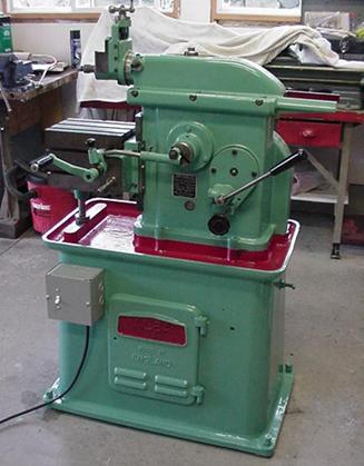
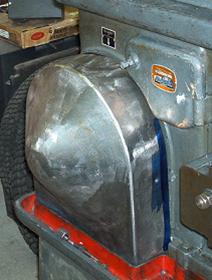
Alba 1A Finished Photo by Pete Verbree
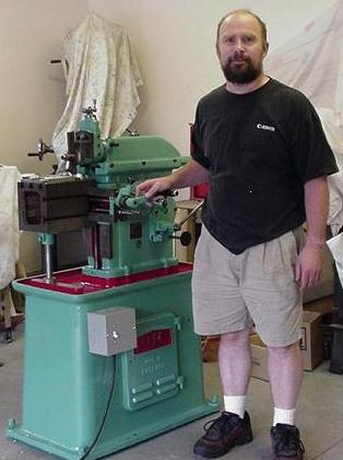
Proud Papa Photo by Pete Verbree
Pete
Keep sending email with questions and interesting shaper stories.
My email address is KayPatFisher@gmail.com.