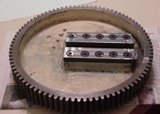
Bull Gear After Repair Photo by Pete Verbree
The first job I tackled was the Bull Gear. This part was originally made from a casting, about 10” diameter and 2” thick with a t-slot cast into a sort of lump near the center. A large part of the top of this t-slot had been broken out. I set this up on my milling machine table and machined off the top of the t-slot to provide a place to bolt on a piece of 3/8” mild steel with ten, 5/16” countersunk cap screws. I installed the plate and screws using Loctite to help hold it all together.
I carefully lined up the gear on the mill table and machined the top surface of the repair piece, flat and level with the rim of the gear, and I then cut a slot into it with a ½” end mill. “Not bad for an amateur!” I say to myself, and so encouraged I closed up shop to contemplate the next repair item.
The clutch housing casting was an interesting shape, basically a plate with two protrusions, one on each side. The inner side held a bushing for a shaft in the reduction drive, a fairly simple piece. The outside on the other hand was more complex. The clutch shaft operates on cam shaped groove that is adjustable. The adjustment utilizes some of those particular English threads. The outer protrusion also housed a shift rod and detent for the high-low gear-shift. More English threads.
I took the casting to a local welding shop for an estimate. “Pretty tough” they said,” lots of cracks and we can’t guarantee good results.” Price about $100.00. Back to the drawing board, more head scratching.
Enter friend and retired machinist George Mckee. I showed the bracket to George. He rolled it over in his hands a couple of times and said “Why don’t you make one out of steel plate, cut the fancy lumps off this one and press them onto a new piece?” Now here was a fix I hadn’t considered! “Why don’t you get a piece of plate cut out to shape, and we’ll lay out the holes on my jig-bore, it’s got a digital readout on it.” Now here was an offer I couldn’t pass up!”
So in due course I had a piece of 7/8” plate cut to shape on a CNC machine and I arrived at George’s shop to watch him do magic. George’s Jig-bore machine is a huge Fosdick of undetermined age with hand wheels as big as my Atlas shaper.
He first took the broken piece (which I had held together with epoxy) and clamped it in the vise. Then he used a dial indicator and zeroed one hole. We used these as coordinates 0,0. We then used the dial indicator and the digital readout to locate each hole on the plate by its coordinates relative to this hole.
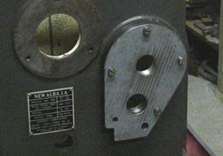
Clutch Housing First Fit Photo by Pete Verbree
The new plate was then swapped for the casting and the holes drilled in accordance with the measurements we had made. I carried the piece home and tried it on the shaper. It bolted right on with ease.
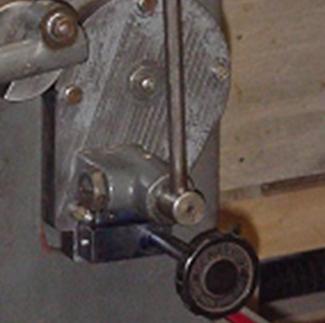
Clutch Housing Press Fit Photo by Pete Verbree
Next step was to cut the parts I wanted off of the original casting. I removed the bulk of the excess material with my “Arm-strong” hacksaw, and I chucked these carefully in the four-jaw chuck. I turned the plate side of each piece into a dowel-like stub that I pressed into the holes bored in the new plate. The outer part was fairly complex and I was not able to utilize the gear-shift detent housing, so I fabricated one from a small piece of steel and attached it with screws.
Two parts down, two to go! The next patient was the most vexing. The ram lever was not original and it did not fit correctly. How was I going to get this vital part to fit?
Remember the manual that friend Frank Dorion sent? It held a valuable clue! In a phantom view of the machine was a profile view of the ram lever. I enlarged this drawing to full size on a photocopier and scaled some dimensions off of it. I compared these to the machine and the existing lever. Pretty close - now I had a plan!
The ram lever is a fairly complex shape: 1½“ thick at the ram attachment end and 1¼“ thick in the body. There are two 1¼“ slots in the body. One for the pivot and one for the siding block that transfers motion from the bull gear. In the head (ram attachment) there is a ¾“ slot to accommodate the upper hinge.
I had our friendly neighborhood welding shop cut the shape from 1¼” plate, and weld two ¼” cheeks on the head.
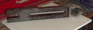
Ram Lever Weldment Photo by Pete Verbree
When I got it home, I clamped it to the mill table and cleaned up one edge and one face. I then blued it up and laid out the slots and holes. It took many hours of hand feeding in the little mill/drill to whittle out the slots and clean up the rest of the part. It wasn’t especially difficult, just time consuming.
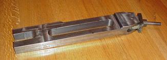
Ram Lever After Machining Photo by Pete Verbree
I took it off the mill, deburred and tried it. Close but not quite. A little more head scratching and I saw what was wrong. Back to the mill, make the lower slot longer, and trim the head shorter. “Hope it fits this time! Sure enough – success!” Buoyed by these recent successes, I moved on to the next part.
The sliding block, which transfers motion from the bull gear to the ram lever, originally was made from steel, and designed to slide in the cast iron ram lever. As I had made the replacement ram lever from steel, I felt that I should make a new block from cast iron.
There are two reasons that I made this decision. First, steel shouldn’t slide on steel, as it tends to gall and wear the sliding surfaces unevenly. Second the slot in the ram lever turned out a little over 1¼” and the original block had too much clearance. I had e-mailed Frank about this and he checked his machine and said that the clearance was about .007”.
I also had some experience with the sliding block on my first Atlas shaper. When I first got it, it clanked badly when I used it under heavy load, so I had made a new block for it, and it improved the performance substantially. I reasoned that since I was making a new block for “Alba” I should try for a close fit.
This turned out to be a pleasant evening’s work with the mill and the lathe. The new block is not as tight as I had hoped, but still well within the .005”-.010” range that I figured was reasonable. (I was aiming for .003”)
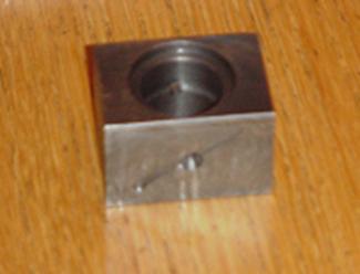
Sliding Block Photo by Pete Verbree
Some re-assembly was the order of the day on the next outing to the shop. This process required a little patience, because of the inevitable re-doing of the step you just thought was completed. All in all it was a fairly straightforward job, making sure that all the parts moved smoothly and the gibs were properly adjusted as I went.
The only area of concern was replacement of some missing fasteners. You’ll recall that they are British Standard Whitworth. I checked with our local fastener supplier, who seems to be able to get just about anything.
“Can you get Whitworth hardware?” I asked. The young guy behind the counter just gave me the “deer in the headlights” look. “Huh?” “British Hardware” I tried again. “Yeah we can order that” comes a voice from the back; one of the senior clerks came to the front and threw a big catalog on the counter.
“Do you know what you need?” he asks. “Yes, ten 5/16 BSW cap screws, 1½” long.” I said. “Just a second” he said, and started typing on the computer. “$4.00 each, 1 week delivery” came the reply.
Well I just about fell off the stool I had perched on, almost half the purchase price of the machine for a few bolts! There had to be another way! The guy behind the counter said, “Why don’t you use standard hardware?” “They’re the same pitch, just different thread pattern.“
I looked at the listing in the catalog and sure enough they were 18tpi, just the same as NC bolts. I left the shop with the 5/16”NC SHCS in hand, having spent a lot less than the cost of two of the other bolts. When I tried the NC hardware, they turned right in, so I added a little Loctite for good measure and things were looking up!
I will describe some final repairs and the first operation next month.
Pete
Keep sending email with questions and interesting shaper stories.
My email address is KayPatFisher@gmail.com.