It was a bit rusty and seized up when he bought it. He cleaned it up and got everything moving.
At first he couldn’t identify it. The only identification (embossed on the cast head) was "Made in England DEPT N".
After some detective work on the World Wide Web, David managed to find out it was an Adept. His model is based on an Adapt shaper that he saw at http://www.lathes.co.uk/adeptshaper/index.html.
They labeled their shapers such as their model 2 as “Adept No2”. His casting only had the remaining letters DEPT N left from the original label due to the machining operations carried out in converting it from a hand operated shaper to a powered shaper.
It is a very small "bench-top" model. The max stroke is about 6 inches with about 4 inches of practical useable stroke.
Cross feed, which is power operated via gears and the usual ratchet device, has about 4 inches of travel.
The head moves sideways, driven by a square threaded leadscrew. The head design is conventional, with vertical slide carrying the clapper box mounted on a swivel.
David has seen plenty of shapers, mostly gathering dust and derogatory comments in dark corners, but has never actually used one. He bought this one because it looked cute and obviously needed someone to rescue it before it rusted to death.
One thing which seems odd to David was that the crank that operates the cross feed is not geared one to one with the main drive crank, so that the cross feed will occur at a varying point in each cutting stroke. He counted the teeth to figure out the gear ratios exactly. The cross feed is geared down by a factor of 4 via 2 pairs of 20 and 40 tooth gears. The main ram is geared down by 24 to 86 teeth so that the ratio is not quite 4. He wonders if someone made a clerical error and produced a batch of 86 tooth gears in place of 96! It would be possible to correct the error and preserve the same tooth size and gear centers by changing the gears to 22 and 88, respectively.
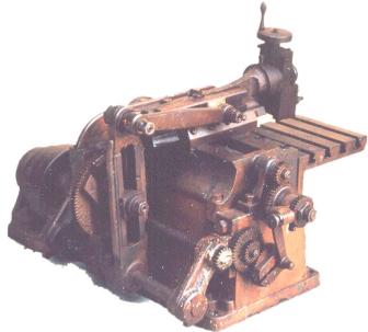
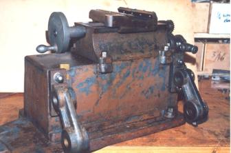
Shaper as Received - Feed Side Photo by David
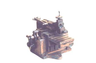
Shaper as Received - Front View Photo by David
David speculates that the hole in the gusset under the table is a part of the table support system, which is missing.
To me the most unusual thing about this shaper is that the knee stays stationary while the ram moves sideways in a carriage mechanism.
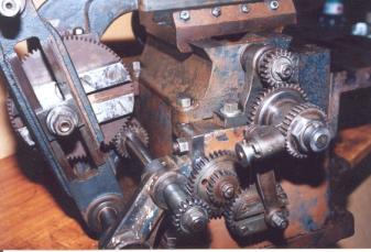
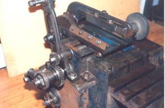
Drive and Feed Mechanisms Photo by David
The photo above shows the drive and feed mechanisms with the ram and connecting link removed.
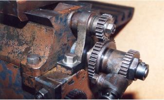
Feed Clutch Photo by David
In the close up of the feed mechanism above the large gear in the center contains a torque limiting friction clutch. This device is to prevent the machine from destroying itself if the operator fails to stop the feed before it reaches the end of the travel. On some shapers the threads on the cross slide screw are removed near the ends to prevent such a crash. Many shapers have no protection at all. I would think that, with the possibility of the clutch slipping, attempting to correct the gear ratios would be non-productive. David thinks that there should be little chance of slippage because the normal amount of friction in the cross travel is very low.
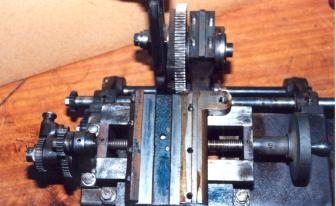
Top with Ram Removed Photo by David
Most Adept shapers were manual. Models were released that had been converted to power. This is the most complex powered shaper that Adept ever produced. It looks like the carriage is the same as on a manual machine but rotated 180 degrees. A lug, which holds the fixed pivot bolt for the hand lever system, is now used to secure the bridgepiece.
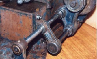
Bridgepiece Linking Drives Photo by David
In the photo above, note the “bridgepiece” linking the carriage with the drive mechanism. The main “chassis” casting is probably identical to that used on the manual machine. The left hand end of the carriage leadscrew is supported close to the drive gear by a special casting bolted to the base box.
Rear Quarter View Photo by David
In the photo above the flat belt pulley has been removed. The keyway in the upper shaft transmits power to the drive system. The lower shaft is stationary and acts as a guide for the lower end of the slotted drive arm.
Rear with Drive Removed Photo by David
As David started rebuilding the shaper and removed the drive mechanism, it was necessary to do some shimming of the two mounting brackets for the drive mechanism as the two horizontal shafts must be parallel to the carriage dovetail.
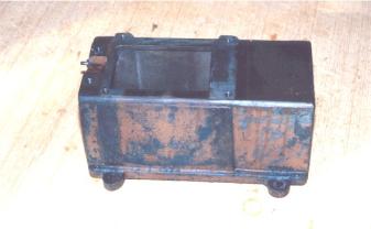
Base Box Photo by David
When you strip machines down to their fundamental parts they start to look pretty simple as in the base box above. But this is necessary for a thorough cleaning and that new paint job.
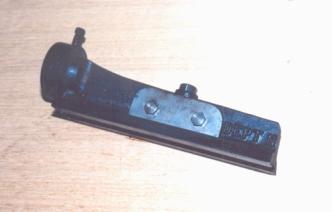
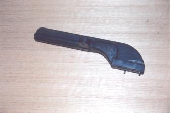
Ram Right Side Photo by David
In the photo of the ram above note the lettering “DEPT N” left on the casting from original “ADAPT NO 2”. The long slot through which the hand-operated lever would pass is behind the clamp plate.
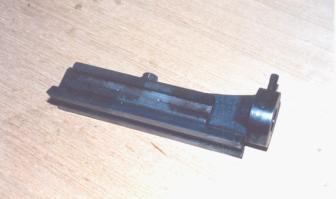
Ram Left Side Photo by David
Bolted to the ram left side is a tee slot piece with serrations to provide a positive location for the pivot bolt.
Bridgepiece Photo by David
The bridgepiece, which links the carriage to the drive mechanism is connected quite solidly being keyed, bolted, and pinned.
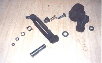
Drive Mechanism Dismantled Photo by David
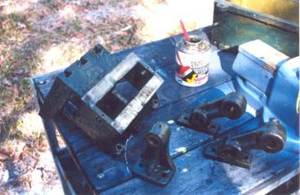
Stripping Paint Photo by David
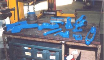
Parts After Painting Photo by David
After weeks of work cleaning, stripping, and painting; a selection of parts (pictured above) is completely restored and ready for assembly. The blue color he chose is turning out a bit brighter than the original color as judged from the remnants of paint.
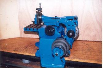
Completed - Right Side Photo by David
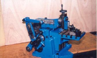
Completed - Left Side Photo by David
The pictures above show the shaper painted and reassembled. Gears and other unpainted components have been chemically blackened. Traditionalists might be offended as the manual Adept shapers were usually black. David prefers bright cheerful colors for machines as it is easier to keep them clean, and in photography it is easier to distinguish the workpiece from the machine.
Thank you David for another great shaper story.
Keep sending email with questions and interesting shaper stories.
My email address is KayPatFisher@gmail.com.