Pepperell Crank Up
10 July 2011
Slide show >> HERE
and video here >> ![]()
Hooray! At last a weekend day that is bright and sunny. What a welcome change.
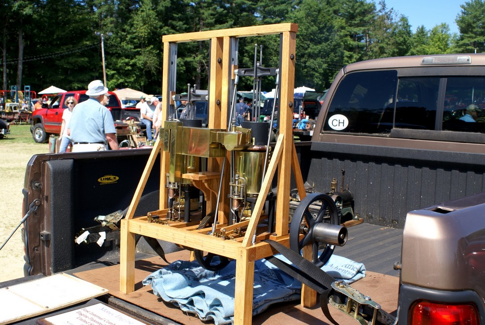
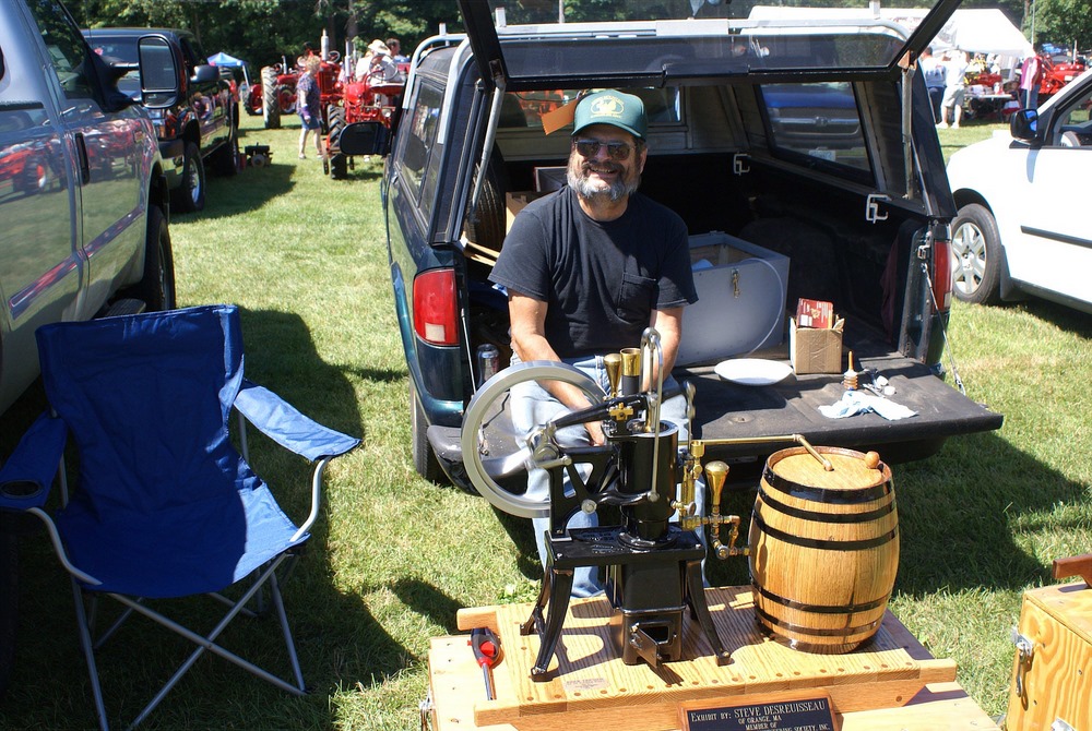
This collection of various electrical and mechanical devices are meant to demonstrate a variety of principles. They were displayed by Earl Russell of Groton MA. Earl has generously taken time to write up the following descriptions of the devices. Thank you so much Earl!
 The main item in the picture is an electric fly ball governor
speed control. The same principle as the governor used to control RPM in most
steam engines. Upon acceleration the weights swing the arms out drawing a free
moving collar up the shaft. The collar is connected to a light dimmer control by
two lines run over pulleys. As the shaft speeds up, the collar rises and the
lines connected to the light dimmer reduce the current decreasing rotational
speed. Speed may be controlled by weight and position of the balls and by the
attachment to the dimmer control. The tension on the spring that brings the
dimmer into the full on position may also be varied.
The main item in the picture is an electric fly ball governor
speed control. The same principle as the governor used to control RPM in most
steam engines. Upon acceleration the weights swing the arms out drawing a free
moving collar up the shaft. The collar is connected to a light dimmer control by
two lines run over pulleys. As the shaft speeds up, the collar rises and the
lines connected to the light dimmer reduce the current decreasing rotational
speed. Speed may be controlled by weight and position of the balls and by the
attachment to the dimmer control. The tension on the spring that brings the
dimmer into the full on position may also be varied.
 The item on the right is a typical Geneva drive. If seen from the
front side the mechanism shows a positive locking switch. The Geneva shown is a
four position system. The benefit of the drive is that the driving shaft turns
the output shaft into one of four positions in about 25 to 30 degrees of
circular motion. The additional circular motion of the input shaft locks the
output shaft from any further rotation. This is a particularly good device in
setups subject to lots of vibration. Don’t attempt to construct a Geneva
unless you have a miller and a rotary table.
The item on the right is a typical Geneva drive. If seen from the
front side the mechanism shows a positive locking switch. The Geneva shown is a
four position system. The benefit of the drive is that the driving shaft turns
the output shaft into one of four positions in about 25 to 30 degrees of
circular motion. The additional circular motion of the input shaft locks the
output shaft from any further rotation. This is a particularly good device in
setups subject to lots of vibration. Don’t attempt to construct a Geneva
unless you have a miller and a rotary table.
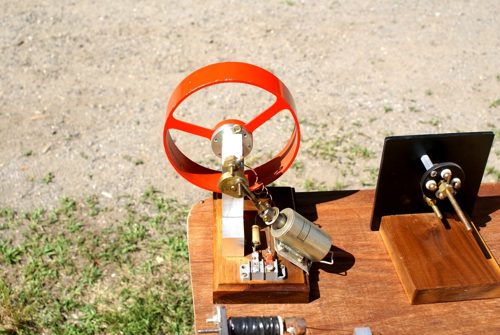
The device with the orange fly wheel is what I refer to as an electric "one lunger". When a small pin rotating with the shaft hits a brass brush assembly the solenoid is activated and turns the flywheel. The brush assembly is a piece of thin brass sheet bent in such a way that the pin contacts it at the proper point of rotation to keep the engine turning. The brass brush is bent in such a way that the amount of revolution with the pin connected can be varied setting the speed. The barely visible brass loop seen at the top of the device controls the contact period and hence the speed.
 Another example of a simple electric motor uses four small pieces
an iron rod placed at 90 degrees on a brass cross. As the armature turns, a
brush contacts a pin closing the circuit to the magnetic poles. The iron slugs
are in position at closure that draws them to the poles. As the slugs reach the
poles the circuit is interrupted and the flywheel effect rotates the shaft until
the pin again excites the poles at the right position for the next slugs. A
large flywheel would smooth out the rotational jitter.
Another example of a simple electric motor uses four small pieces
an iron rod placed at 90 degrees on a brass cross. As the armature turns, a
brush contacts a pin closing the circuit to the magnetic poles. The iron slugs
are in position at closure that draws them to the poles. As the slugs reach the
poles the circuit is interrupted and the flywheel effect rotates the shaft until
the pin again excites the poles at the right position for the next slugs. A
large flywheel would smooth out the rotational jitter.

 These two pictures show a radio loose coupler used in early reception. When
these devices were used there was no such thing as an amplifier. The signal had
to be detected strictly from the level received.
These two pictures show a radio loose coupler used in early reception. When
these devices were used there was no such thing as an amplifier. The signal had
to be detected strictly from the level received.
As there was very little selectivity in the early sets it was essential to get maximum detection of the desired signal. To do this the impedance of the primary and secondary coils was made variable. To this end the number of active turns in both coils was made adjustable. One control on the secondary coil allowed a coil change of ten turns while another allowed one turn changes. The number of active turns in the primary was also made adjustable. For maximum power transfer the source impedance must match the load impedance. The primary impedance should be adjusted to match the impedance of the antenna system while the secondary impedance should match the detector load. Coupling between the primary and secondary was varied by inserting the primary coil inside the secondary coil by selected amounts. If the coupling was too tight signals could not be separated. If too loose, insufficient energy would be taken in. Tuning a receiver was not a trivial operation.
To complicate the problem, the received signal had no intelligence or modulation. The signal was a series of broken continuous wave bursts. To create a useful signal a "ticker" was introduced between the detector and the headset. This device chopped the continuous wave signal at an audio rate, generally around 700 cycles. The detected continuous wave signal was now received as an audio note. It was now possible to employ Morse code in communication.

 This mechanism is known as a "Hooke’s Coupler". It can transmit
rotary motion between two shafts at any angle up to 90 degrees. As the input
shaft is rotated the bent pins move in and out of the holders rotating the
output. The coupler shown here has a transmission angle of 37 degrees. The holes
must be very accurate to allow smooth rotation requiring precision machining.
This mechanism is known as a "Hooke’s Coupler". It can transmit
rotary motion between two shafts at any angle up to 90 degrees. As the input
shaft is rotated the bent pins move in and out of the holders rotating the
output. The coupler shown here has a transmission angle of 37 degrees. The holes
must be very accurate to allow smooth rotation requiring precision machining.
 In the early days of radio many different materials and mechanical devices were
tried to improve detection. The Gelena crystal and the cat’s whisker were
known to most crystal radio builders. Less known were other crystals and a setup
using a fine platinum wire barely touching the surface of a cup of acid.
Carborundum was found to rectify if under sufficient pressure. The device shown
was such a clamp with a spring in the bottom of the enclosure and a torque screw
adjustment for the upper plate.
In the early days of radio many different materials and mechanical devices were
tried to improve detection. The Gelena crystal and the cat’s whisker were
known to most crystal radio builders. Less known were other crystals and a setup
using a fine platinum wire barely touching the surface of a cup of acid.
Carborundum was found to rectify if under sufficient pressure. The device shown
was such a clamp with a spring in the bottom of the enclosure and a torque screw
adjustment for the upper plate.
In the background of the picture is a work in progress. A turbine wheel built by soldering pennies to a disk is to be driven by a nozzle. The energy to power this nozzle will be a steam generator. The small DC motor removed from an old tape recorder makes a very linear generator.


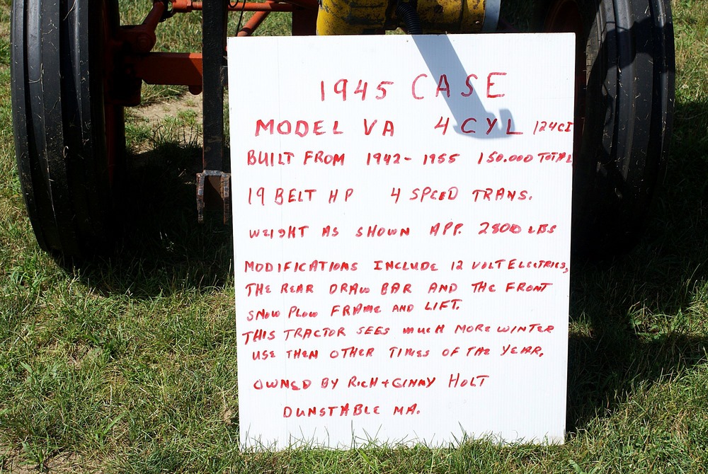
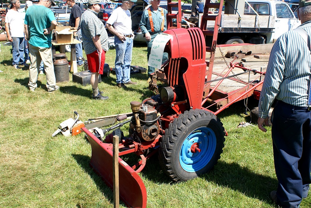
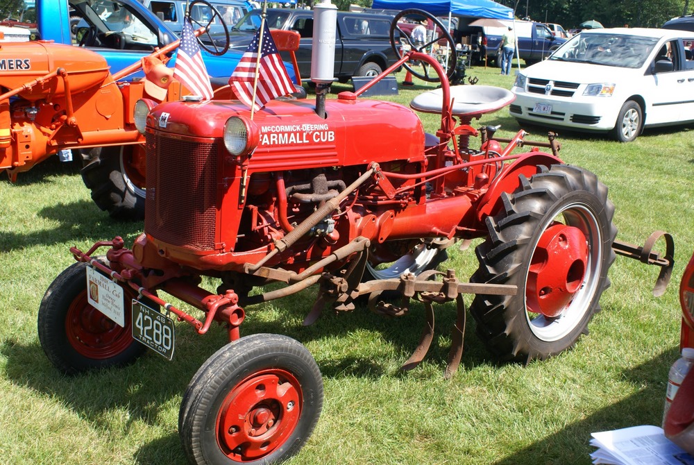
 I bought a raffle ticket to win this tractor, which I need like a bass needs a
bicycle.
I bought a raffle ticket to win this tractor, which I need like a bass needs a
bicycle.


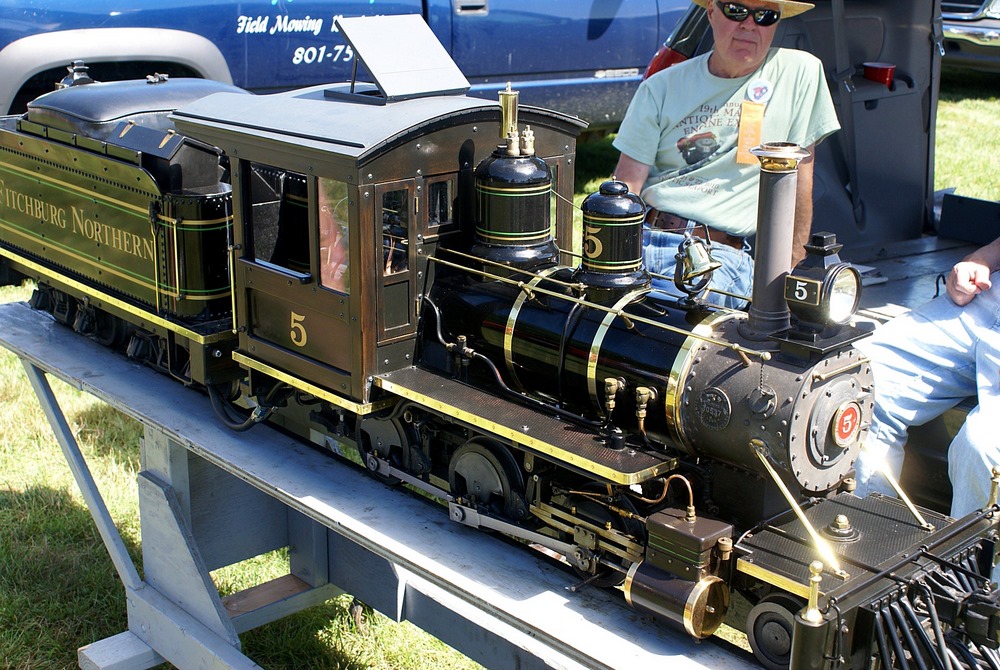


 Russ Steeves' beautiful Fitchburg Northern